Micromouse Robot
An autonomous micromouse-style robot developed for SER300 Mechatronic Design, combining STM32 embedded programming, custom PCB design, sensor feedback, encoder-based turning, motor control, and iterative mechanical development across three major robot revisions.
Project Overview
Project Overview
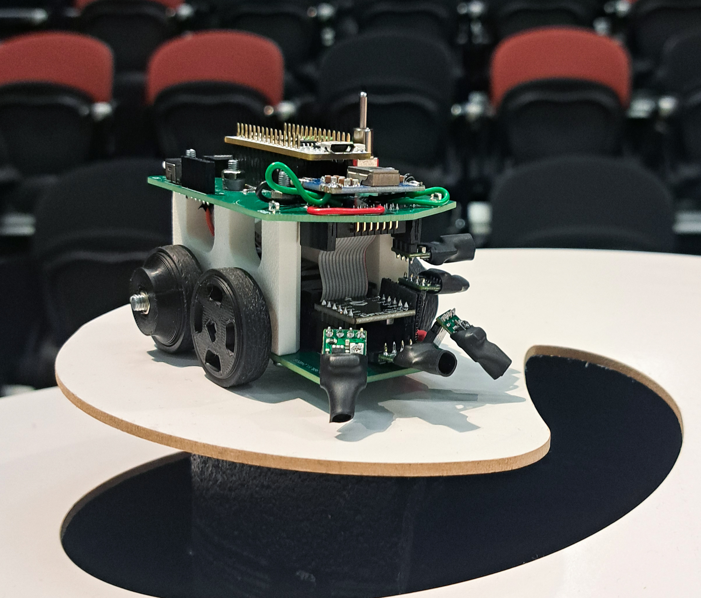
Theseus 3 was the final iteration of my autonomous micromouse-style robot developed for SER300 Mechatronic Design. The project challenged students to design, build, program, and test a small autonomous robot capable of navigating a physical obstacle course using sensor feedback and embedded control logic.
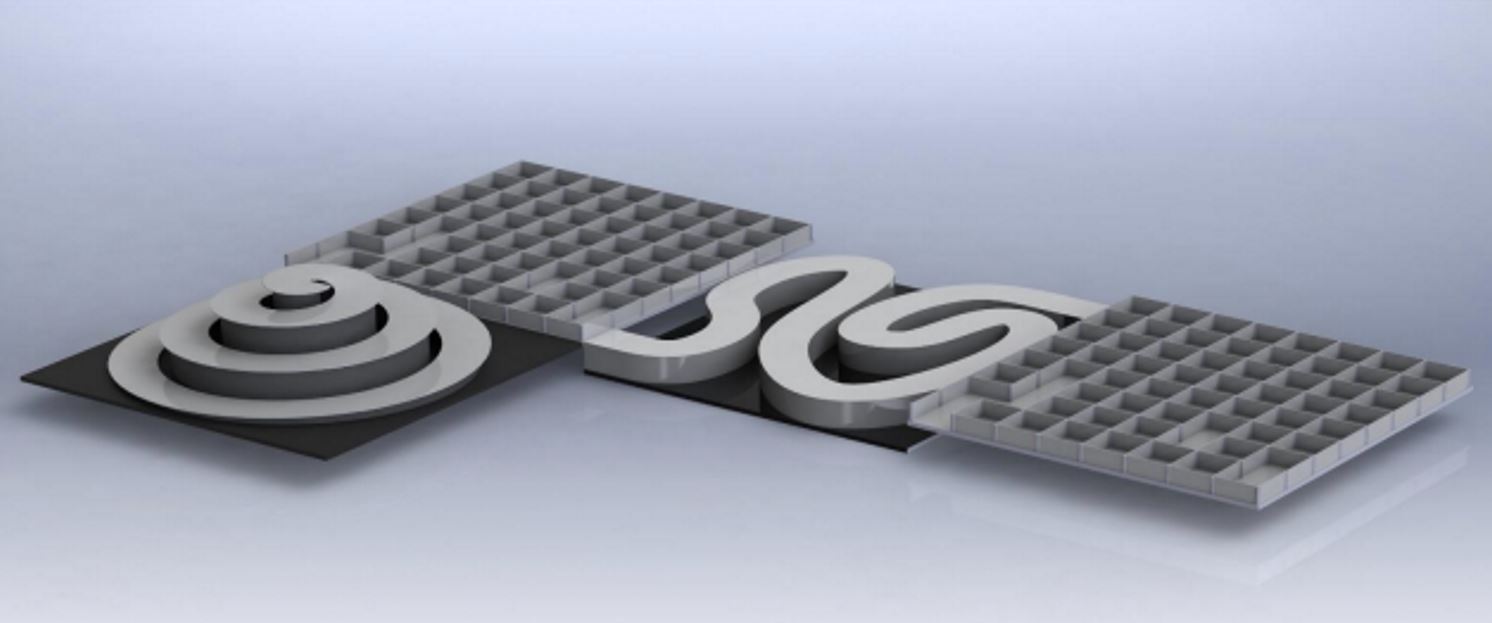
The course required more than simple straight-line driving. The robot had to respond to maze cells, raised causeway sections, transitions between course features, and a spiral incline. This made the project a practical exercise in mechatronics integration, where mechanical packaging, PCB design, sensor selection, motor control, firmware structure, and calibration all affected the final result.
The robot evolved through three major revisions: Theseus 1, Theseus 2, and Theseus 3. Earlier concepts were more ambitious and included more complex sensor and PCB designs, but these became difficult to progress within the available timeframe. The final robot was simplified into a more achievable system based around an STM32 Nucleo controller, custom two-level PCB structure, N20 motors, encoder feedback, IR proximity sensors, and state-machine-driven firmware.
While the final demonstration did not result in a complete flawless course run, the project became one of my most valuable embedded robotics learning experiences. It gave me practical exposure to PCB design, SMD soldering, STM32CubeIDE, timer interrupts, PWM motor control, encoder feedback, sensor calibration, and debugging a physical robot under real constraints.
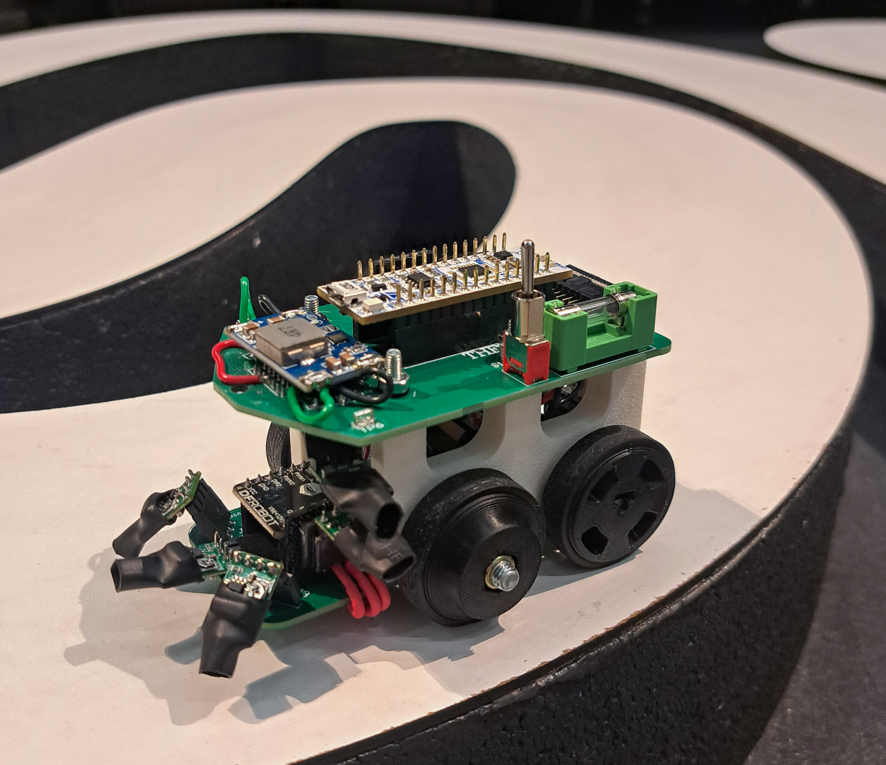
Final Robot Demonstration
The behaviour shown in this test represents the core of the project: reading proximity sensors, evaluating the current maze condition, entering a drive state, and using motor control and encoder counts to perform forward movement and turning manoeuvres.
Key Features
Design Iteration
A major part of this project was the process of iteration. The final robot was not the first design, but the result of several revisions that gradually reduced complexity in favour of reliability, manufacturability, and the ability to test quickly.
Theseus 1 and Theseus 2 explored more ambitious concepts, including more complex sensing, denser PCB layouts, surface-mount hardware, and I2C devices. These designs were valuable learning exercises, especially for PCB design, datasheet interpretation, footprint selection, SMD soldering, and board bring-up.
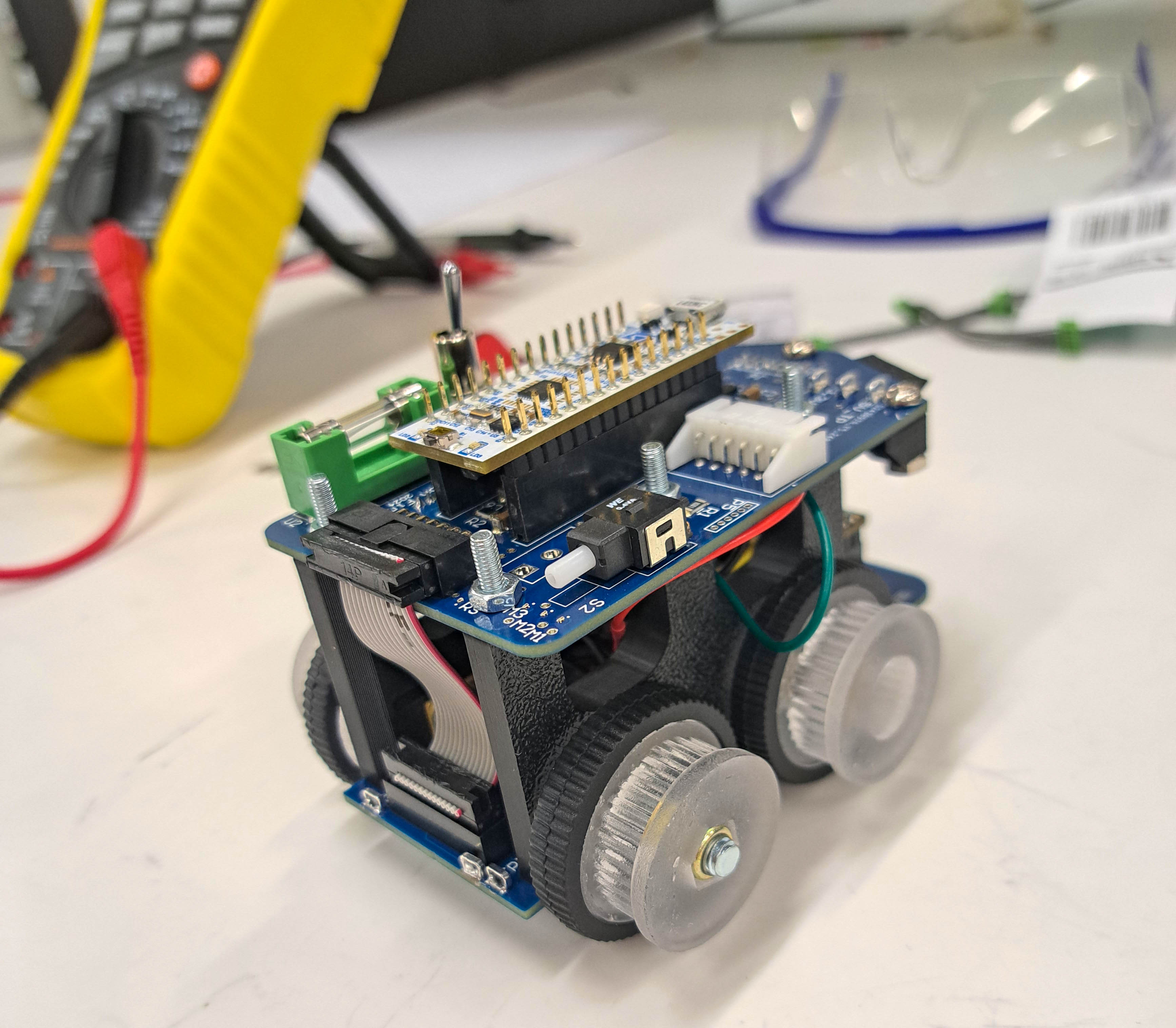
As the project progressed, the design was simplified into Theseus 3. This final version focused on a more achievable combination of binary IR proximity sensing, encoder-assisted motor control, a custom two-board PCB structure, and firmware built around a sensor evaluation function and drive state machine.
Course Requirements
The micromouse course combined multiple physical challenges. Maze cells required the robot to identify wall conditions and make turning decisions. Raised causeway sections required the robot to keep correcting its direction while travelling along a constrained path. The spiral incline introduced a traction and stability challenge, especially as the robot climbed the banked upper section.
This made the project more difficult than simply programming a robot to follow a line or drive straight. The robot had to recognise different course states, transition between them, and respond to imperfect sensor feedback while maintaining enough mechanical stability to continue moving.
Mechanical Design
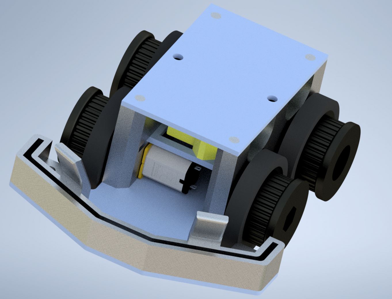
The mechanical design was built around a compact four-wheel robot body with a rounded front profile. From early in the design phase I leaned toward a four-wheel layout, similar to a small conventional vehicle. This decision influenced the robot footprint, motor placement, PCB layout, and eventual two-level body structure.
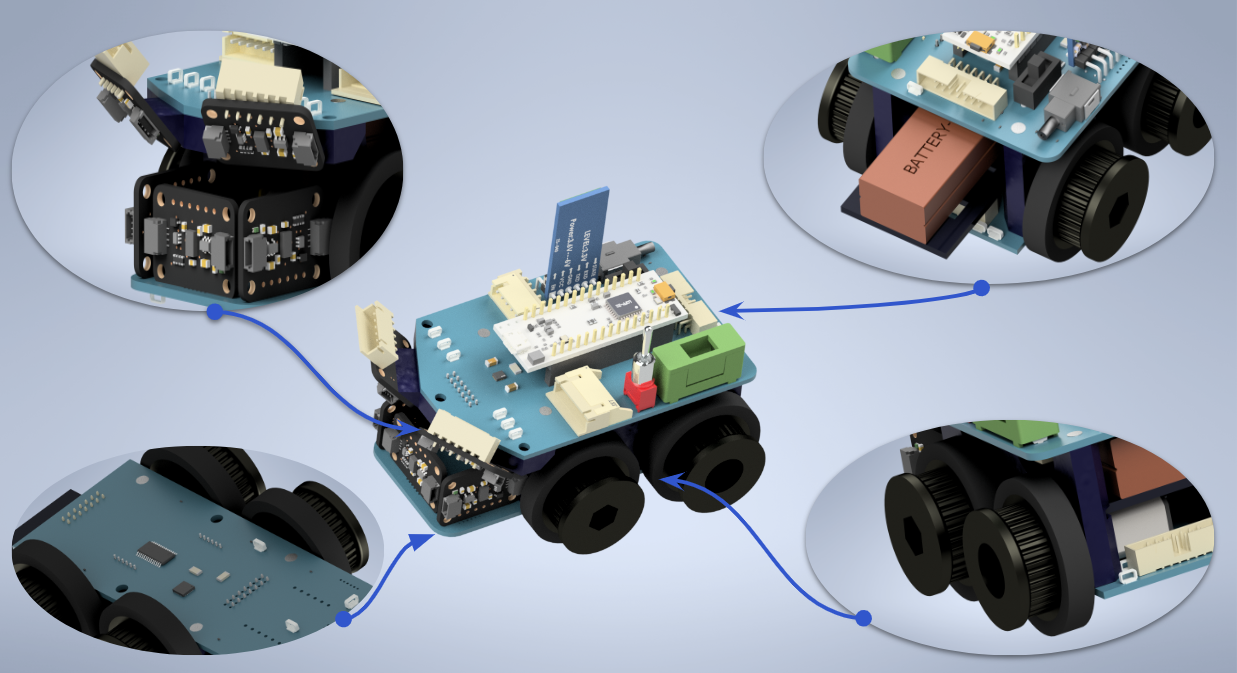
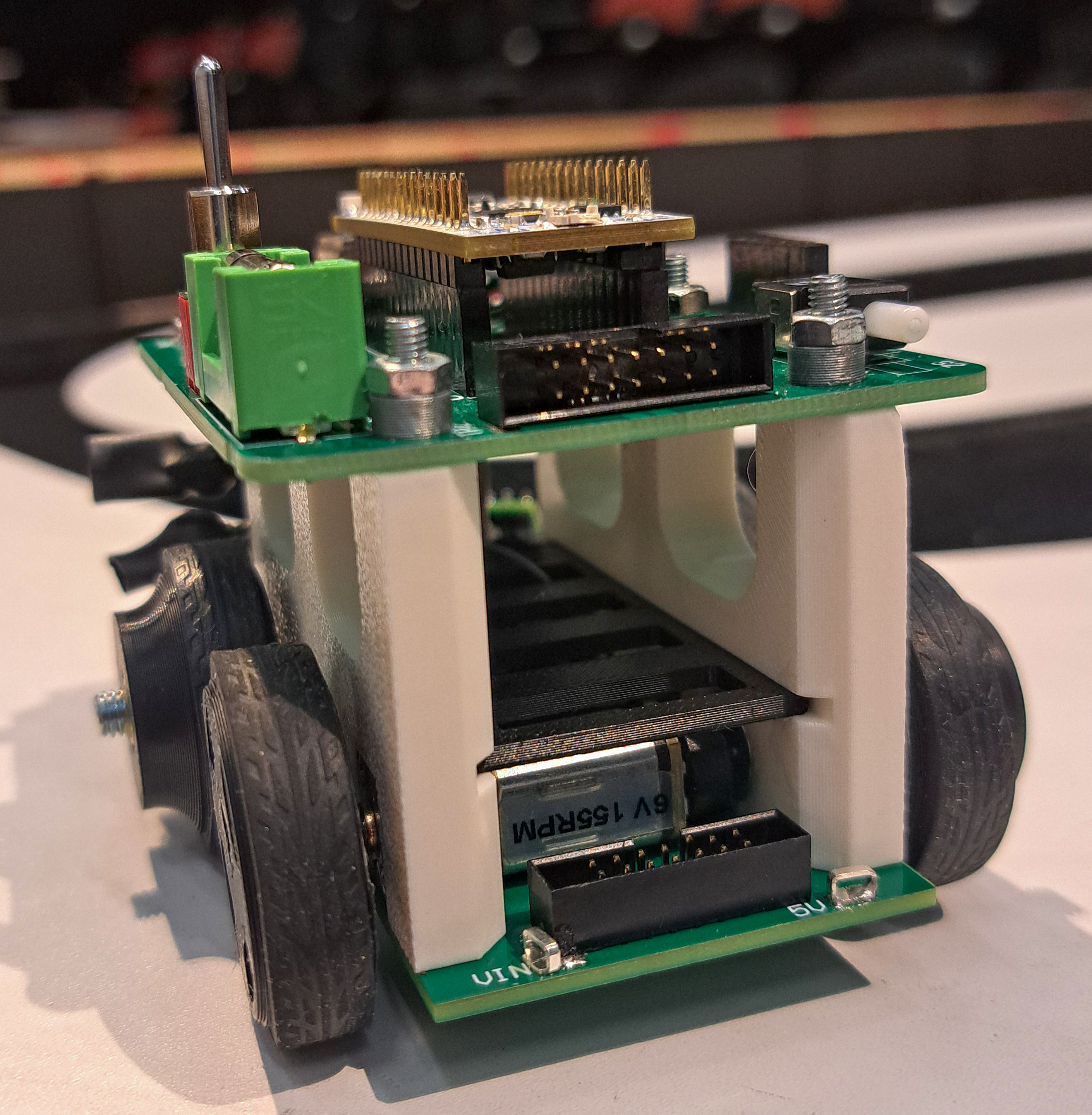
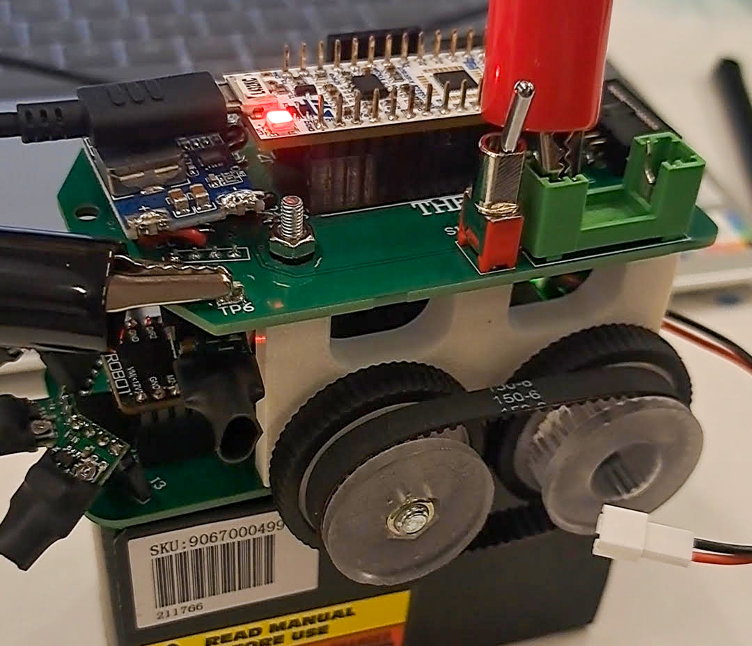
The final robot used two stacked PCB levels supported by 3D printed side walls. These side walls provided rigidity, supported the upper and lower PCB layers, housed the N20 motors, and created internal space for wiring. A sliding divider was used to keep the motor wiring and connectors contained, while also leaving a protected space for a compact 2S LiPo battery.
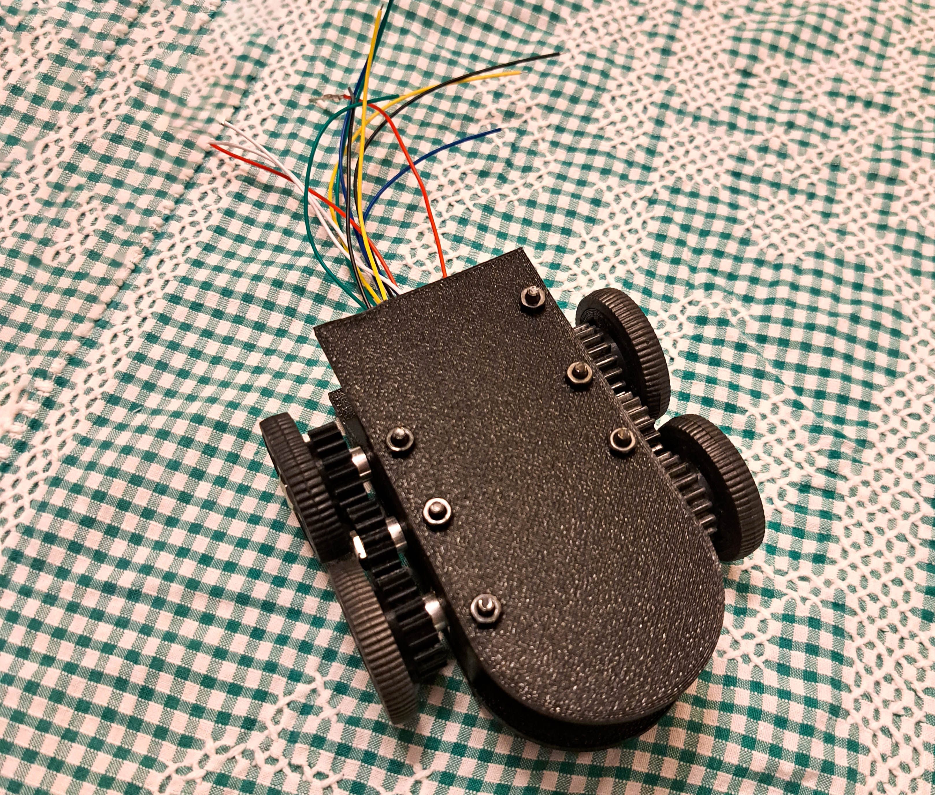
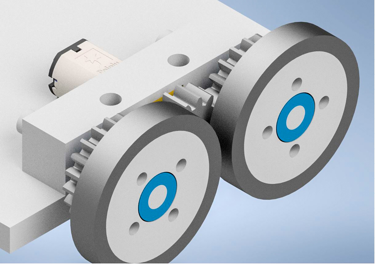
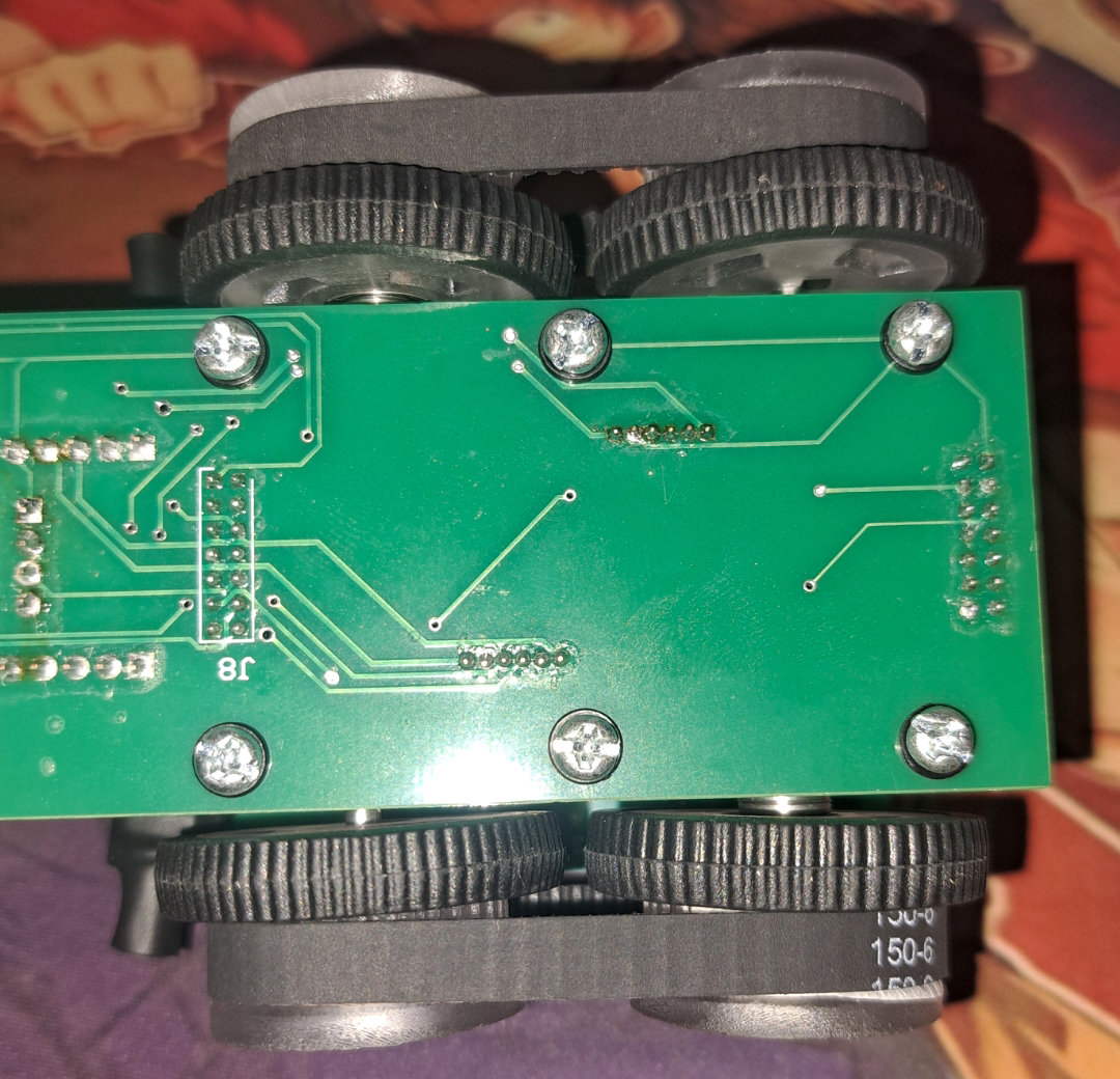
The drivetrain went through several concepts. The first idea was to link wheel pairs with gears, including an intermediate gear so both wheels on each side would rotate in the same direction. This proved difficult due to the resolution and tolerance limits of small 3D printed gears. A timing belt and pulley arrangement was then explored, but belt tension introduced bending forces on the motors and affected driving consistency.
The final solution removed the linked wheel pairs and used two powered wheels with two free-spinning wheels. This made the robot simpler and faster to complete, but introduced trade-offs in traction, slippage, and turning accuracy, particularly on the spiral incline.
Sensor System
The sensor system changed significantly throughout the project. Early ideas included through-hole IR emitters with phototransistors, surface mount IR emitter and phototransistor pairs, and time-of-flight sensors. These options had the advantage of potentially providing more detailed distance information, but also increased the electrical and software complexity.
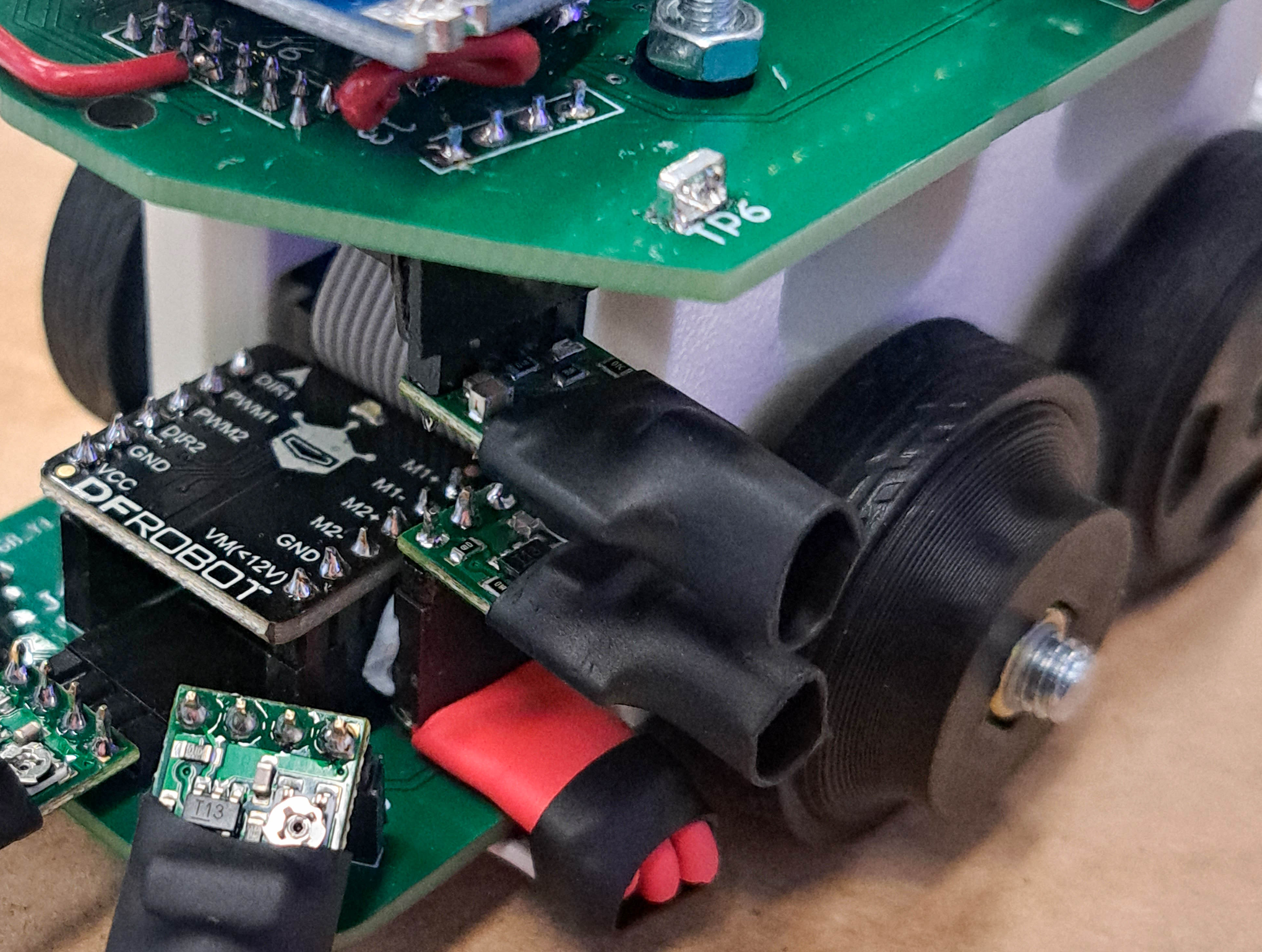
The final Theseus 3 design used Pololu 38 kHz IR proximity sensors. This was a more achievable solution within the timeframe, but it meant the robot was working mostly with binary detection rather than measured distance. Instead of knowing that a wall was at a specific distance, the robot largely knew only whether a wall was detected or not detected.
This made calibration one of the most important parts of the project. Sensor placement, wall distance, detection threshold, and the physical dimensions of the robot all affected how reliably the robot could detect maze walls and course edges. In hindsight, an analogue or distance-based IR solution would have provided more useful feedback for wall following and alignment.
Technical Development
Electrical Design
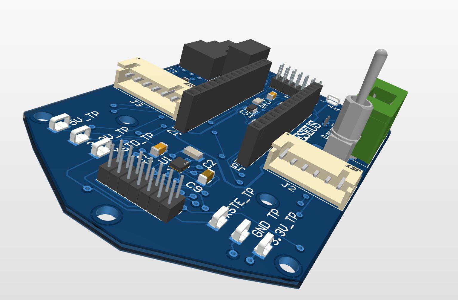
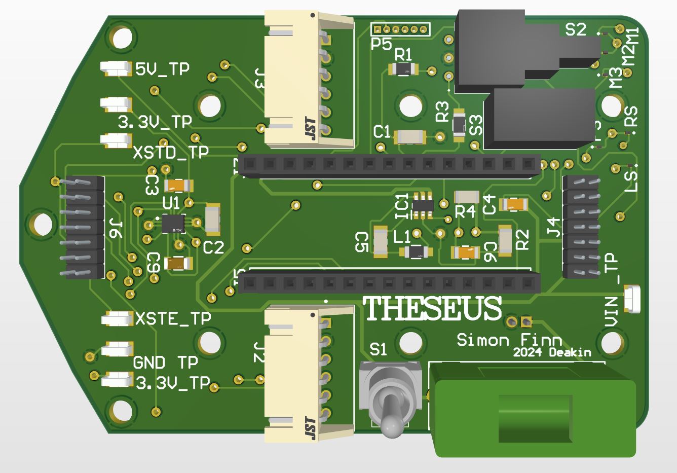
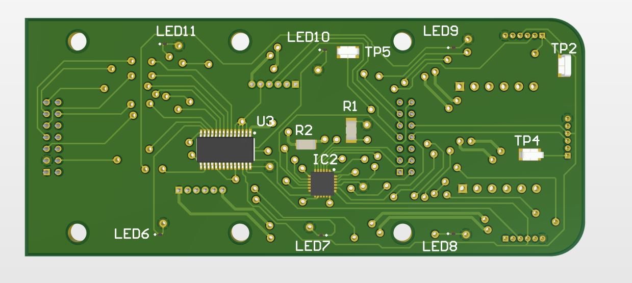
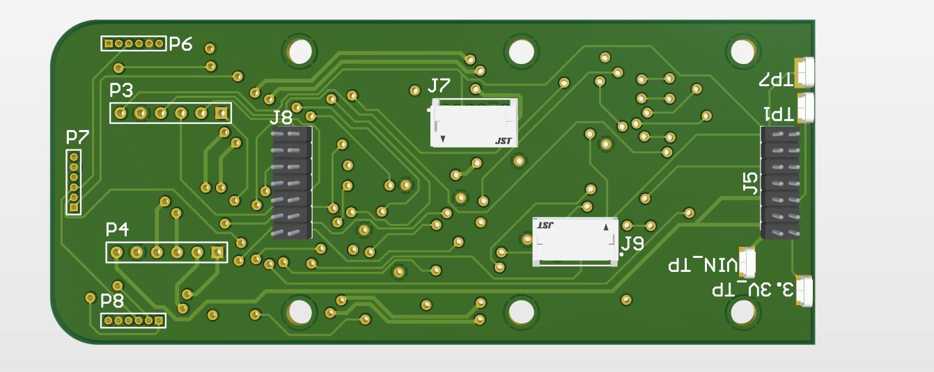
The electrical design became one of the largest parts of the project. The final system used a custom pair of PCBs, with an upper and lower board connected using IDC connectors. This allowed power and signals to pass between the two levels while keeping the robot compact and serviceable.
Earlier revisions explored more complex surface-mount components, including a GPIO expander, inertial measurement unit, LED driver, and time-of-flight sensing. While these features were eventually simplified out of the final robot, they gave me valuable practice with component selection, datasheets, SMD soldering, footprint creation, and I2C communication.
I initially designed a pair of four-layer boards with internal planes for 3.3 V and ground. This helped reduce routing complexity and gave me experience with a more advanced PCB stack-up. For the final Theseus 3 revision, I moved to a pair of two-layer boards with ground pours, partly because the simplified design no longer required a four-layer solution and partly because two-layer boards had a shorter manufacturing timeframe.
The robot required multiple voltage levels: 3.3 V for the IR proximity sensors, 5 V for the motor driver, encoders, and Bluetooth module, and battery input voltage for the Nucleo VIN supply path. A compact 2S LiPo battery powered the robot, with a fuse and switch included to make testing safer and more predictable.
Embedded Software
The firmware was written for an STM32 Nucleo board using STM32CubeIDE. The initial software concept was more complex because it needed to interface with multiple I2C devices and other peripherals. As the sensor system was simplified, the final firmware became more focused around reliable sensor reading, state evaluation, and motor control.
The final software can be summarised as three main parts. First, a timer-based interrupt periodically updated the robot's sensor values. Second, an evaluation function analysed those sensor values to determine what condition the robot was currently in. Third, a drive state machine acted on that decision and commanded the motors accordingly.
A timer interrupt was used to sample the five proximity sensors at a consistent interval. Motor control was handled using PWM output from a timer peripheral, while direction pins controlled whether the wheels drove forward, reversed, or rotated against each other for turning. Encoder feedback was handled using GPIO interrupts connected to Hall effect sensors on the motors, allowing turns and movements to be tuned using counts rather than fixed delays alone.
Core firmware structure
// High-level structure used by Theseus 3

while (EntryCondition == true)
{
  Evaluate_Sensors();  // Interpret current sensor readings
  Drive_State();       // Run the motion state selected by the sensor logic
}

// Timer interrupt
// Periodically calls Update_Sensors()

// GPIO interrupts
// Increment encoder counts when motor encoder pulses are detected

// PWM timer
// Controls motor speed through the motor driver
Sensor Evaluation and Drive State Machine
The sensor evaluation function compared the current readings from the front, left, right, and angled sensors. Different sensor combinations represented different course conditions, such as a left wall only, a front wall, walls on both sides, an open cell, or a condition where one of the angled sensors no longer detected the surface.
Once a condition was identified, the software assigned a state number. The drive state machine then used that state number to choose the appropriate behaviour. Some states drove the robot forward with a slight correction, while others reversed, turned using encoder counts, corrected clockwise or anticlockwise, or stopped the motors if an unexpected sensor combination occurred.
This approach gave the robot a structured decision-making system even though the final sensor information was limited. The result was not a full maze-solving algorithm in the competitive micromouse sense, but it was a practical embedded state machine that could demonstrate maze-cell navigation and course correction behaviours.
Project Outcome
Testing and Performance
The final demonstration did not go as cleanly as intended, mainly due to sensor calibration issues on the day. The final IR sensors provided binary wall detection rather than measured distance, so the robot's behaviour was highly dependent on the exact spacing between the sensors and the maze walls.
Despite this, Theseus 3 was able to demonstrate several important behaviours individually. It could solve several maze cells before calibration drift led it astray, recognise and correct when transitioning between maze and causeway sections, perform corrective driving within the causeway, recognise the transition back into the maze, and partially correct while climbing the spiral incline.
The spiral exposed one of the main mechanical compromises in the final design. Earlier drivetrain concepts aimed to link the wheels using gears or timing belts, but these created their own reliability issues. The final version used two powered wheels and two free-spinning wheels, which made the robot easier to complete but reduced traction and contributed to side slip on the banked upper section of the spiral.
In the end, the project was less about presenting a perfect competition robot and more about learning what makes an embedded robotic system reliable. Theseus 3 brought together custom hardware, firmware, sensors, motors, mechanical design, and real-world testing into a single working prototype, even if the final outcome fell short of the original goal.
What I Would Improve
If I were to revisit this project, the first improvement would be the sensor system. A distance-based or analogue sensing approach would provide more useful information than simple binary wall detection, allowing the robot to better estimate its position within each cell and perform more consistent wall following.
I would also redesign the drivetrain around symmetrical powered wheels, improved traction, and more reliable transmission geometry. The final offset powered-wheel arrangement helped simplify assembly, but it created compromises during turning and on the spiral section.
I would also allow more time for track-specific calibration. The embedded logic was capable of demonstrating the required behaviours individually, but micromouse-style robots depend heavily on repeated physical testing, small parameter changes, and tuning under the same conditions they will face during demonstration.
From a software perspective, a stronger future version would move beyond the course-state approach and toward a more structured navigation strategy. This could include better cell tracking, more reliable distance sensing, and eventually a true maze-solving algorithm once the sensing and drivetrain were stable enough to support it.
Skills Developed
This project helped develop practical skills across embedded systems, PCB design, mechanical packaging, robotics, debugging, and system integration. It was especially valuable because the final performance depended on the interaction between all subsystems rather than any single discipline in isolation.
Embedded Systems
STM32CubeIDE, timer interrupts, GPIO interrupts, PWM motor control, encoder counting, super loop structure, and state-machine logic.
Electronics and PCB Design
Custom upper and lower PCB design, SMD soldering, connector selection, voltage regulation, power distribution, I2C experimentation, and board-level debugging.
Mechanical Integration
Two-level robot packaging, motor mounting, battery placement, drivetrain iteration, wire management, traction trade-offs, and compact 3D printed structural parts.
Testing and Debugging
Sensor calibration, encoder turn testing, track-based tuning, fault finding, drivetrain debugging, and working through the difference between a designed system and a reliable physical robot.