Sewer Serpent Leak Detection System
An industry placement project focused on documenting and improving a water leak detection system, combining sensor evaluation, custom PCB design, mechanical prototyping, field testing, and engineering recommendations.
Project Overview
Project Overview
This project was completed during an industry placement at Deakin University and focused on the Sewer Serpent leak detection system, a field-deployable system designed to locate compromised PVC stormwater and sewer pipe sections.
The broader project was successful in demonstrating leak detection, but one important limitation remained in the way the system measured probe distance. The existing design used a rotary encoder inside the reel hub, which meant it was measuring reel rotation rather than directly measuring how far the pushrod had travelled through the pipe.
My work focused on investigating, prototyping, and documenting improved distance measurement approaches. This included optical flow testing, custom PCB design, encoder signal conversion, follower-wheel prototyping, field test support, and future engineering recommendations. Additionally all documentation, recommendations and the design of a controlled testing site were my responsibilities.
Project Purpose
The key issue was that reel rotation does not always represent actual pushrod movement. The hose can be fed out while the reel remains partially stationary, slack can form, and the effective diameter of the wound pushrod changes as the reel fills or empties.
For a leak detection system, this distance error matters because the operator uses the displayed probe position to locate where the pipe fault is likely to be. Improving the position measurement would therefore make the system more useful in real field conditions.
The aim was not to redesign the entire product from scratch, but to investigate direct pushrod measurement approaches while keeping the existing system largely intact as a fallback.
Key Features
Test Rig and System Context
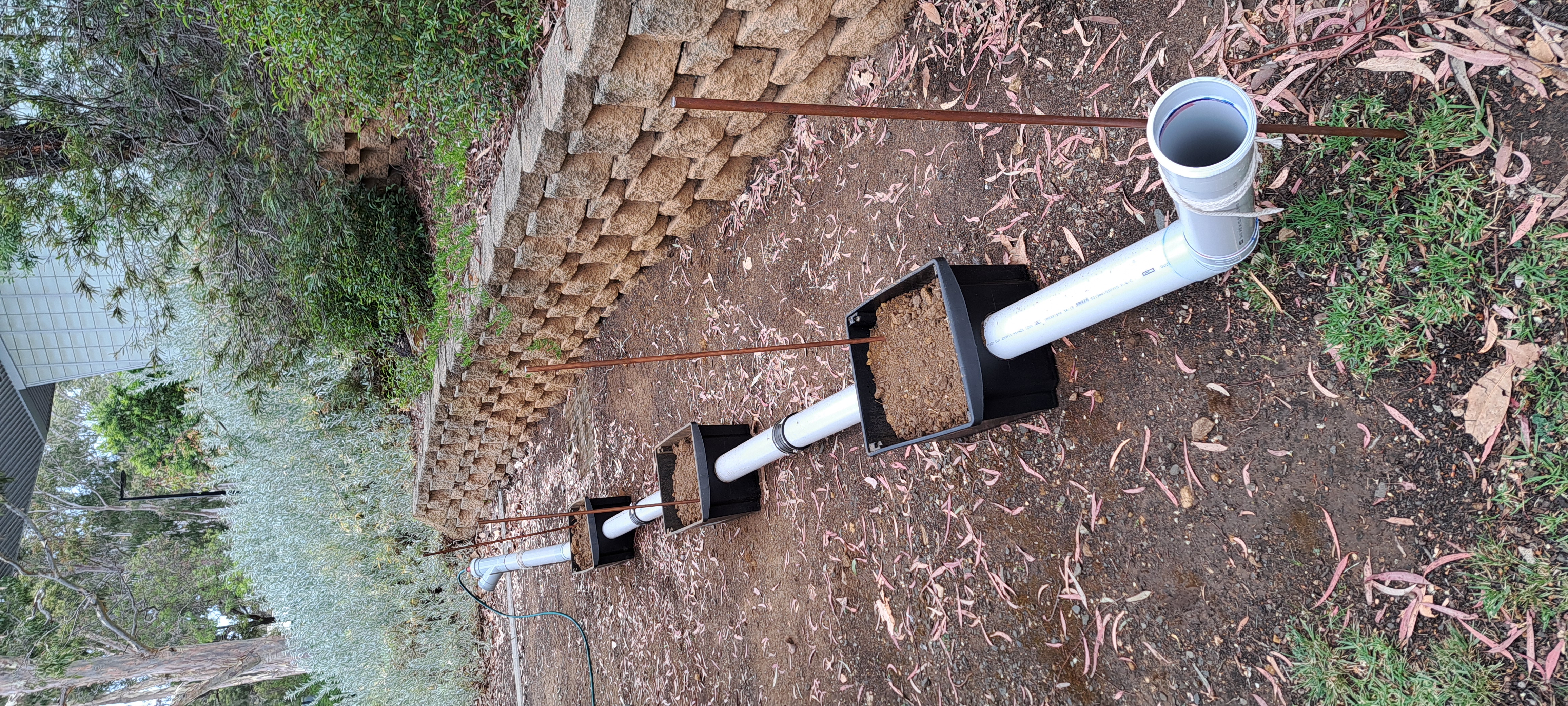
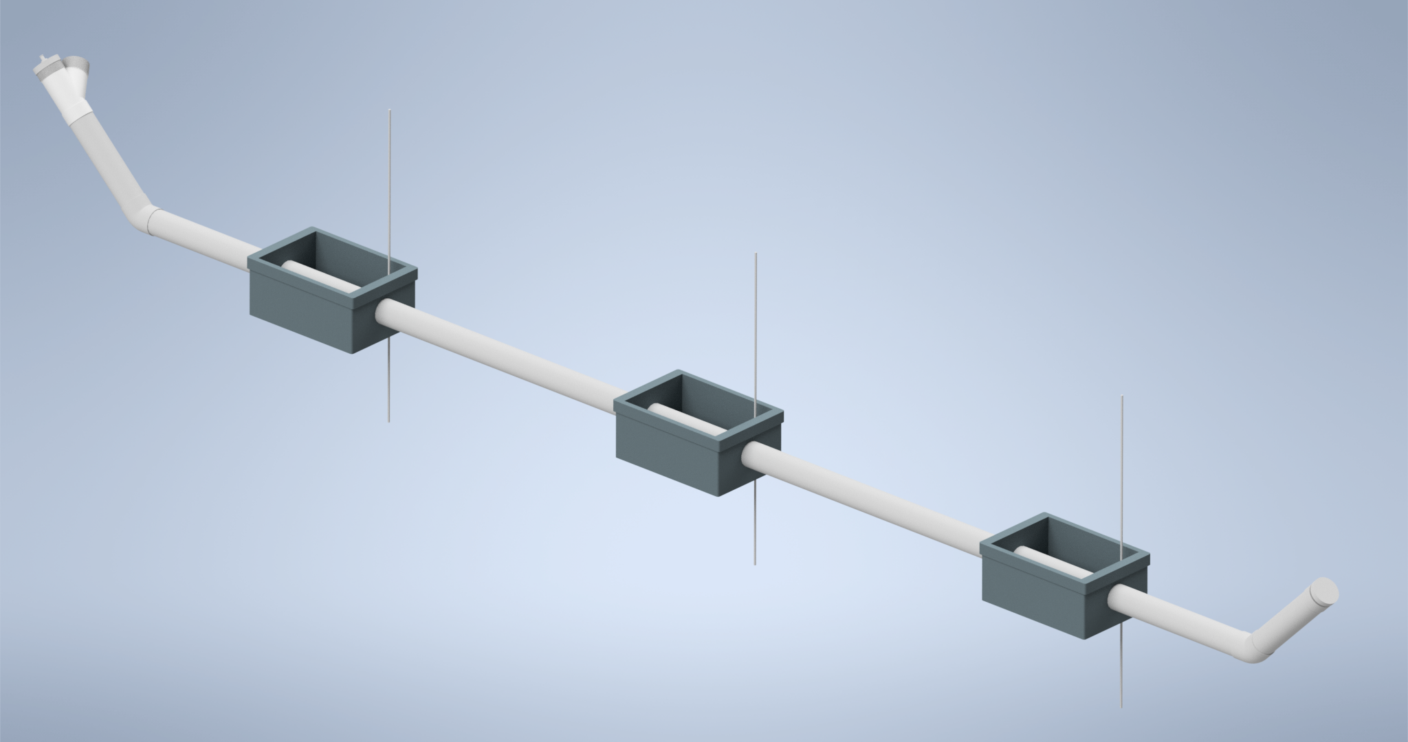
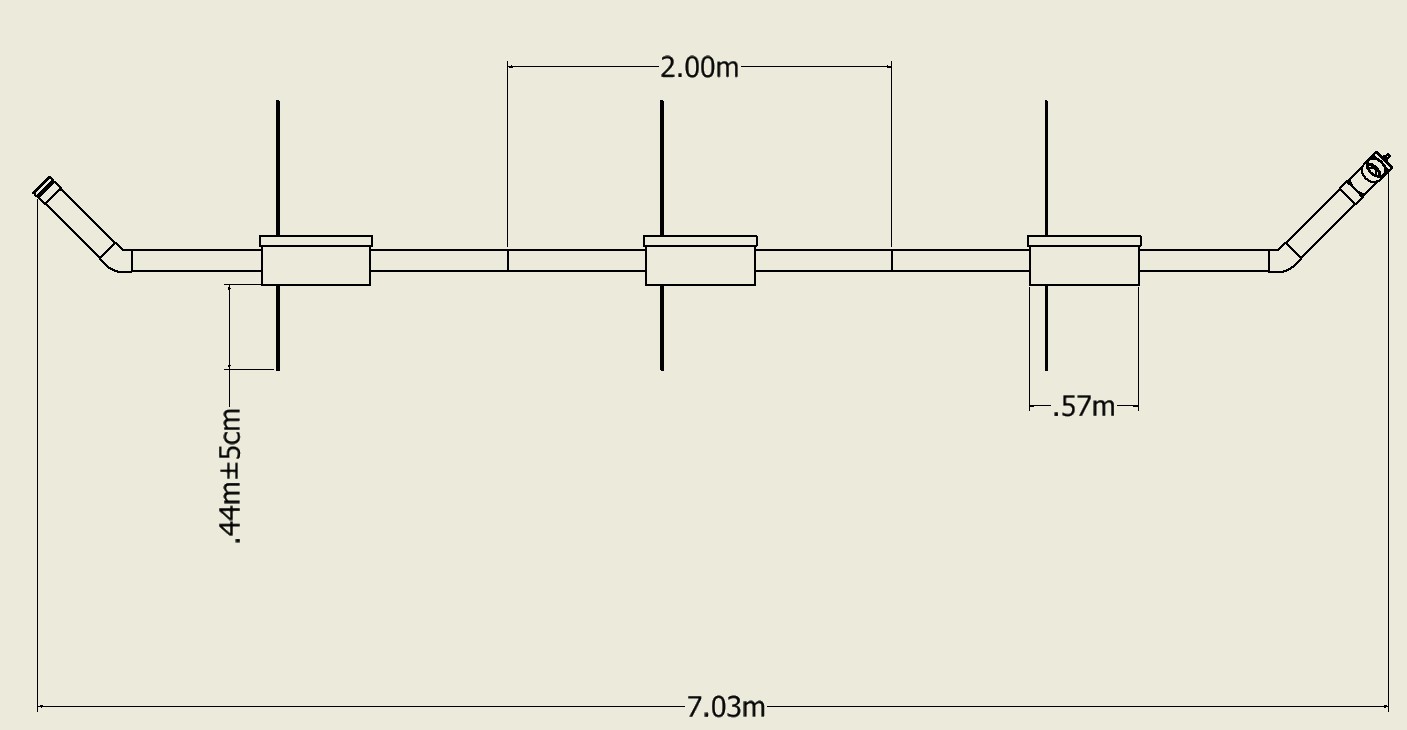
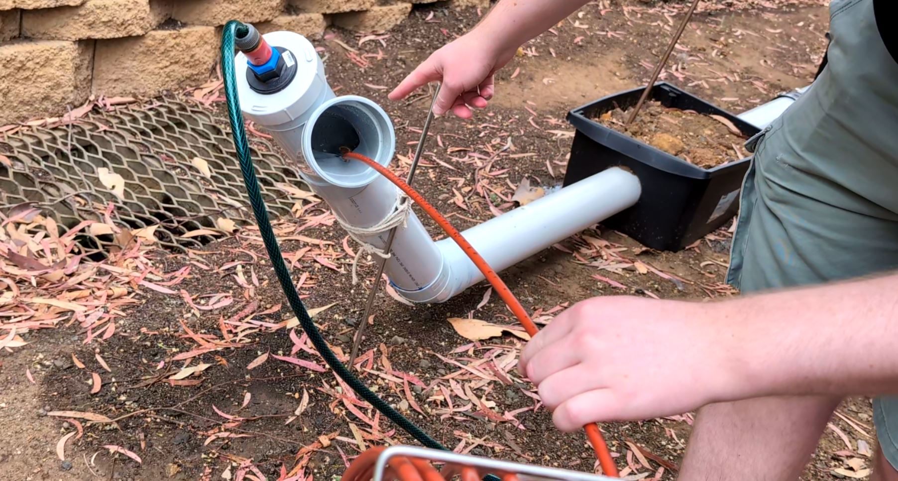
A PVC pipe test rig was assembled to simulate the field setup used by the Sewer Serpent system. The rig included pipe sections, soil boxes, grounding rods, water filling, and a cable reel setup to support repeated testing.
This gave the team a controlled way to test the full workflow, including pipe flooding, grounding, probe movement, scan setup, signal integrity, leak detection, and scan review. The system was housed on-site at the university, requiring the system to remain above ground for easy removal. This led to a design wherein each container housed a leak and a connecting grounding rod.
The field setup also highlighted practical constraints that are easy to miss during bench testing, such as wet environments, cable routing, operator handling, reel movement, grounding quality, and physical access around the test site.
Custom Encoder Interface PCB
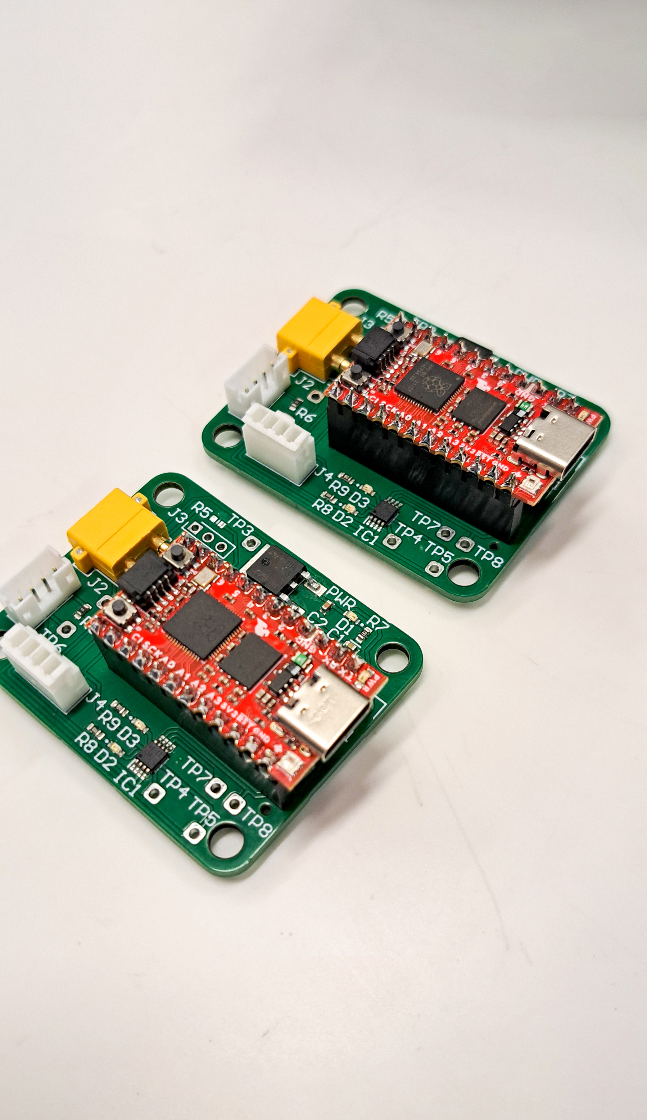
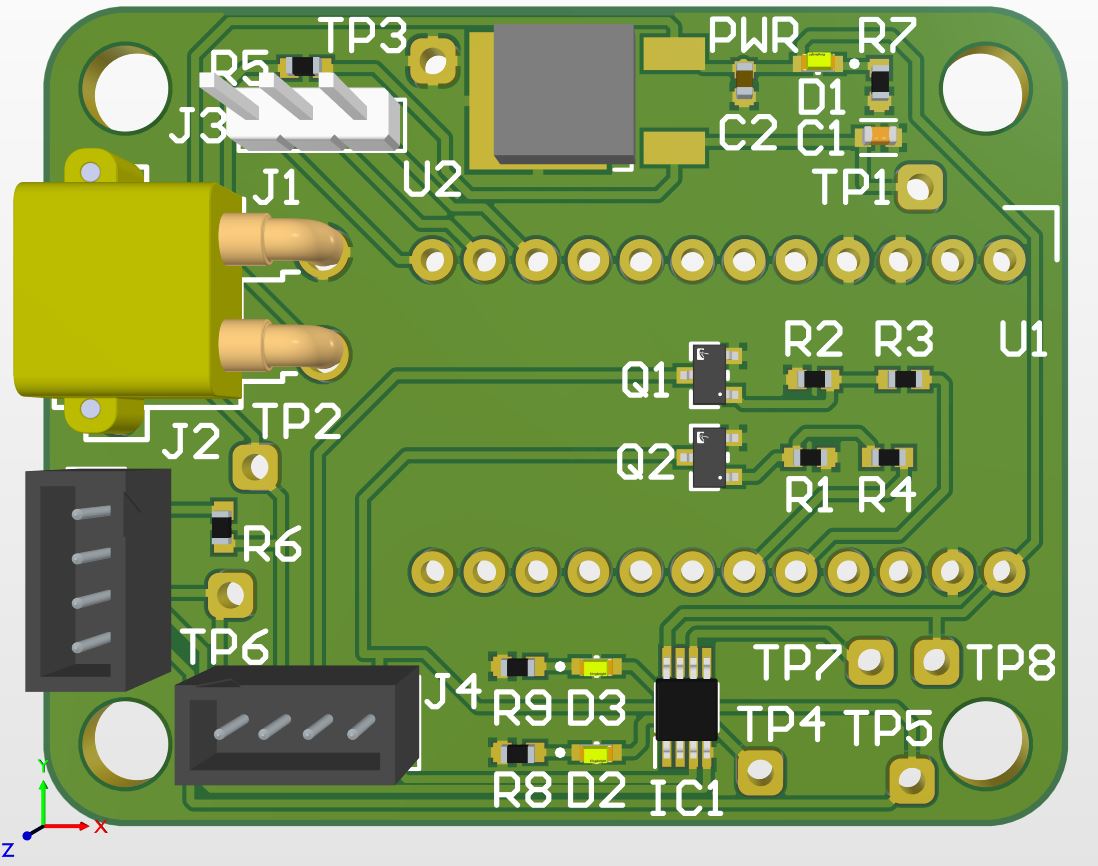
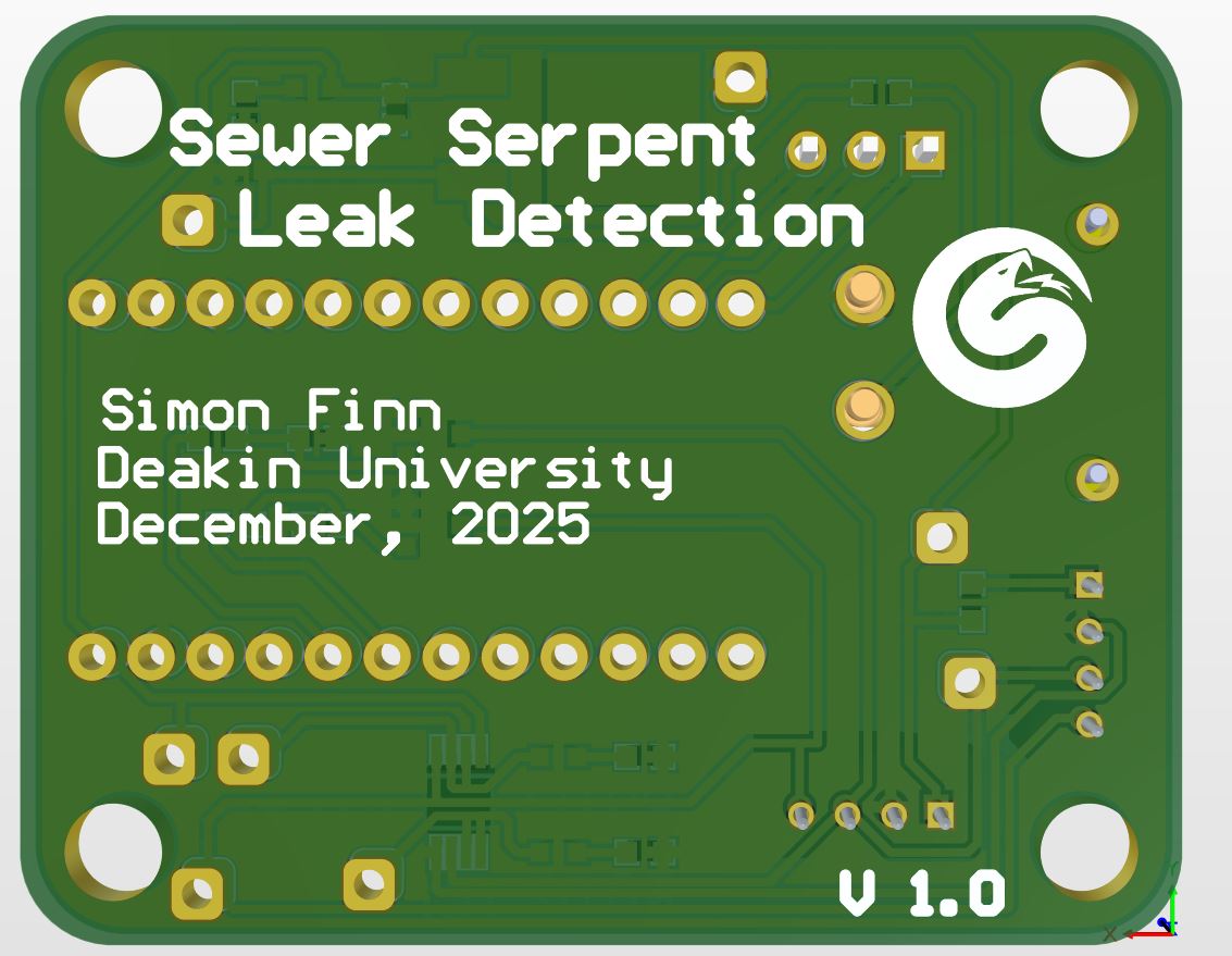
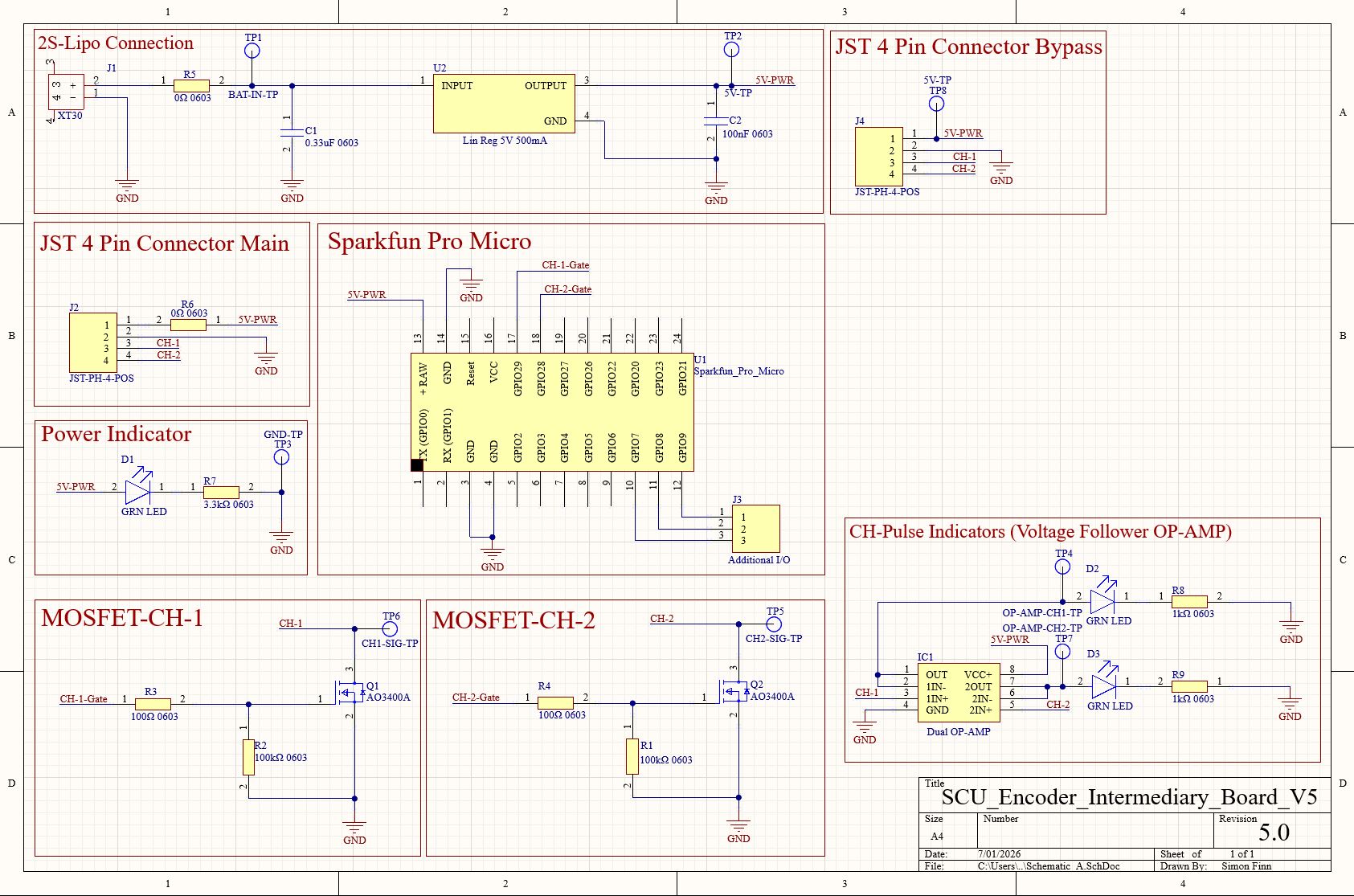
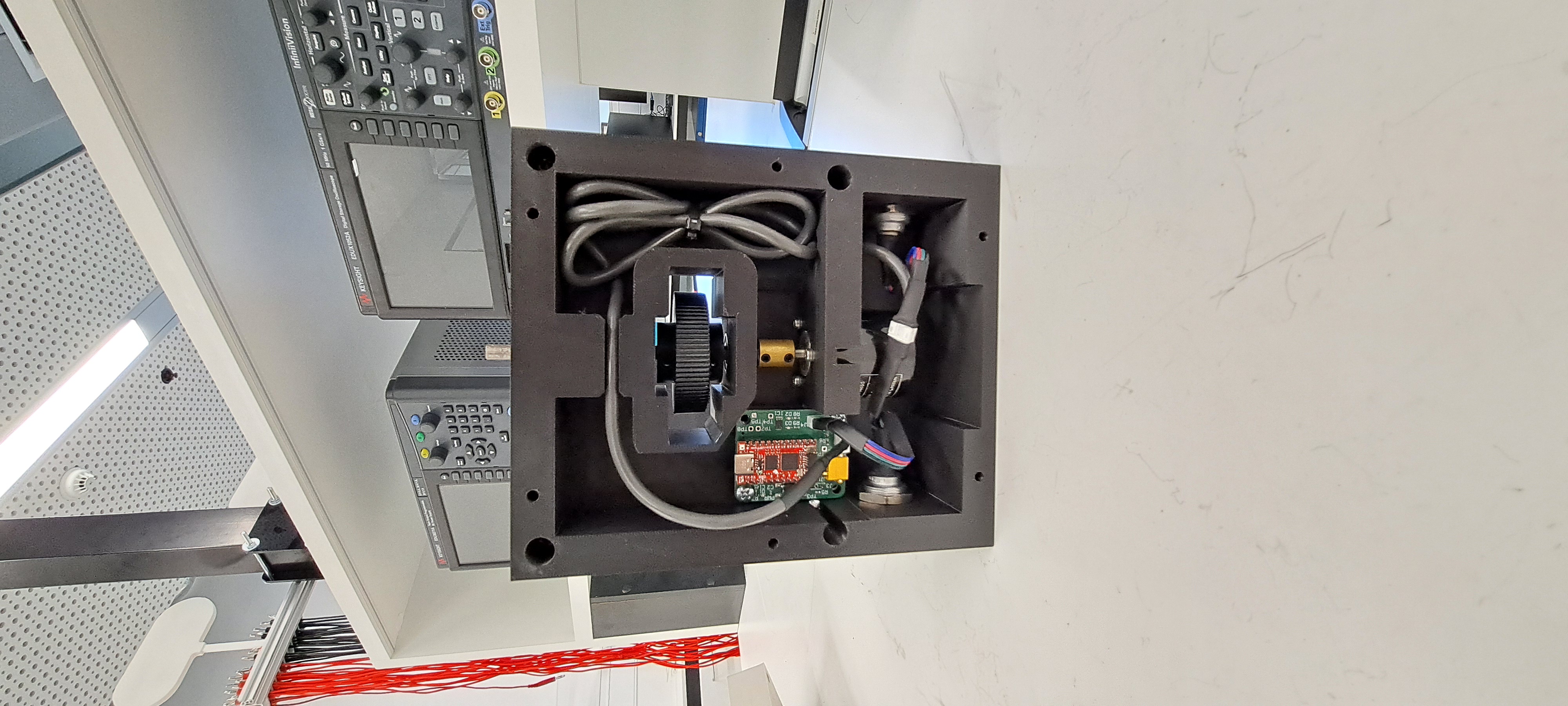
A custom intermediary PCB was designed to support alternative distance measurement approaches. The board used a SparkFun Pro Micro RP2040 and supporting circuitry to output two encoder-style logic channels to the existing Serpent Control Unit.
The PCB included MOSFET switching stages, visual pulse indicators, power input options, test points, and connector breakouts. The goal was to convert data from a new measurement device into the kind of quadrature pulse signals that the control unit already expected.
Although the PCB was originally designed around the optical flow approach, it became a useful flexible platform because the same board could also be reconfigured for a follower-wheel encoder solution.
Follower-Wheel Encoder Prototype
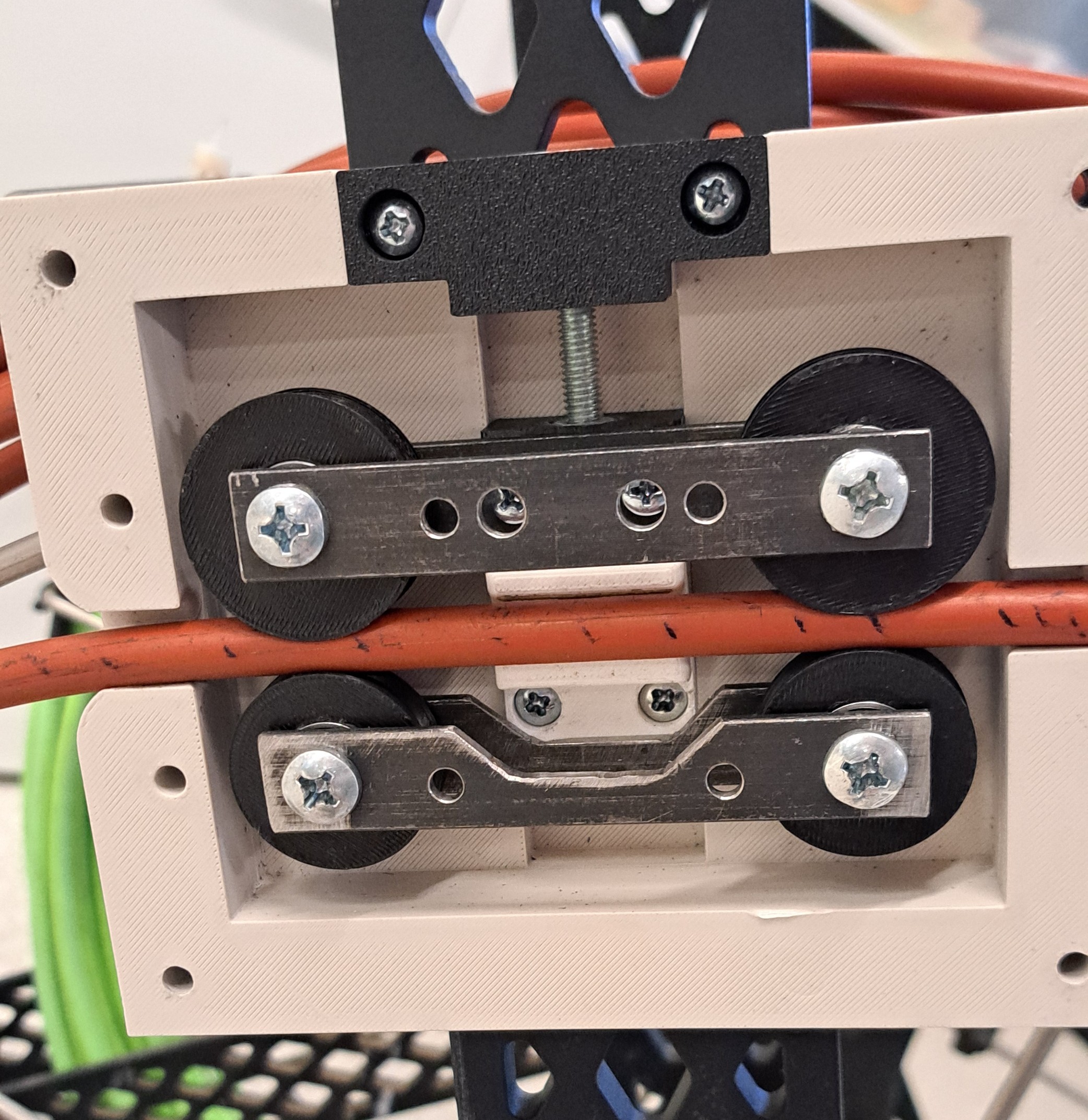
After optical flow testing showed reliability issues at realistic feed speeds, the project shifted toward a mechanical follower-wheel encoder. This approach measured pushrod movement using a wheel pressed against the hose surface.
The prototype used guide rollers and an adjustable clamping mechanism to control contact with the hose. This produced more promising distance readings than the optical flow approach, especially after calibration.
The remaining challenge was mechanical repeatability. Too little clamping force allowed slip, while too much clamping force increased drag and could still produce inconsistent readings. The prototype showed that the concept had potential, but the contact mechanism needed further design refinement.
Technical Development
Optical Flow Investigation
The first direct measurement approach investigated was optical flow sensing. This was appealing because it offered a non-contact way to track the movement of the hose surface, similar to how a computer mouse tracks movement across a desk.
A SparkFun PAA5160E1 optical tracking sensor was evaluated with an RP2040 microcontroller. The sensor was intended to sit close to the hose, track the surface movement, and output distance information that could then be converted into encoder-style pulses for the control unit.
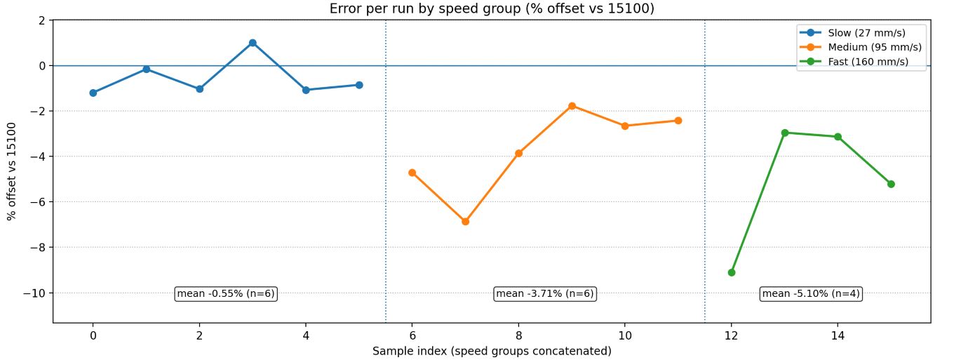
In controlled testing, the optical flow approach showed promise at slow feed rates. However, it became unreliable at more realistic operator feed speeds, which meant it was not suitable as the final measurement approach within the placement timeframe.
Optical flow result
The system achieved low error at slow movement, but the error increased too much at practical pushrod feed speeds. This made optical flow a useful investigation, but not the preferred final direction.
Encoder Signal Conversion
The existing control unit expected encoder-style signals over two channels. To avoid redesigning the control unit, the measurement interface needed to convert alternative sensor data into a familiar quadrature-style pulse format.
The PCB used the RP2040 as the processing stage and MOSFET output circuitry to safely pull the control unit inputs low. This allowed the new measurement system to behave like an external encoder from the point of view of the existing hardware.
This approach kept the modification relatively modular. If one sensing method failed, the same board could be reused for another method, such as a mechanical encoder connected to a follower wheel.
Conceptual signal flow
Pushrod movement
  -> sensor or encoder measurement
  -> RP2040 processing
  -> channel A and channel B pulse generation
  -> MOSFET output stage
  -> Serpent Control Unit encoder inputs
Follower-Wheel Testing
The follower-wheel prototype was tested by moving the pushrod over known distances and comparing the measured value against the expected travel distance. This helped evaluate how clamping force, wheel diameter, and slippage affected accuracy.
The testing showed that a calibrated wheel-based system could produce strong readings, but only when the contact between the wheel and hose was consistent. The prototype was therefore promising electrically and conceptually, but the mechanical contact design was still the limiting factor.
This was a useful outcome because it narrowed the future development path. Rather than continuing with optical flow, the more practical next step would be a mechanically improved follower or belt-contact encoder system.
Follower-wheel result
The follower-wheel approach was the more promising direction, but the prototype still suffered from slip and clamping sensitivity. A future version would need better contact area, grippier materials, or a belt-contact mechanism.
Operating Procedure and Field Testing
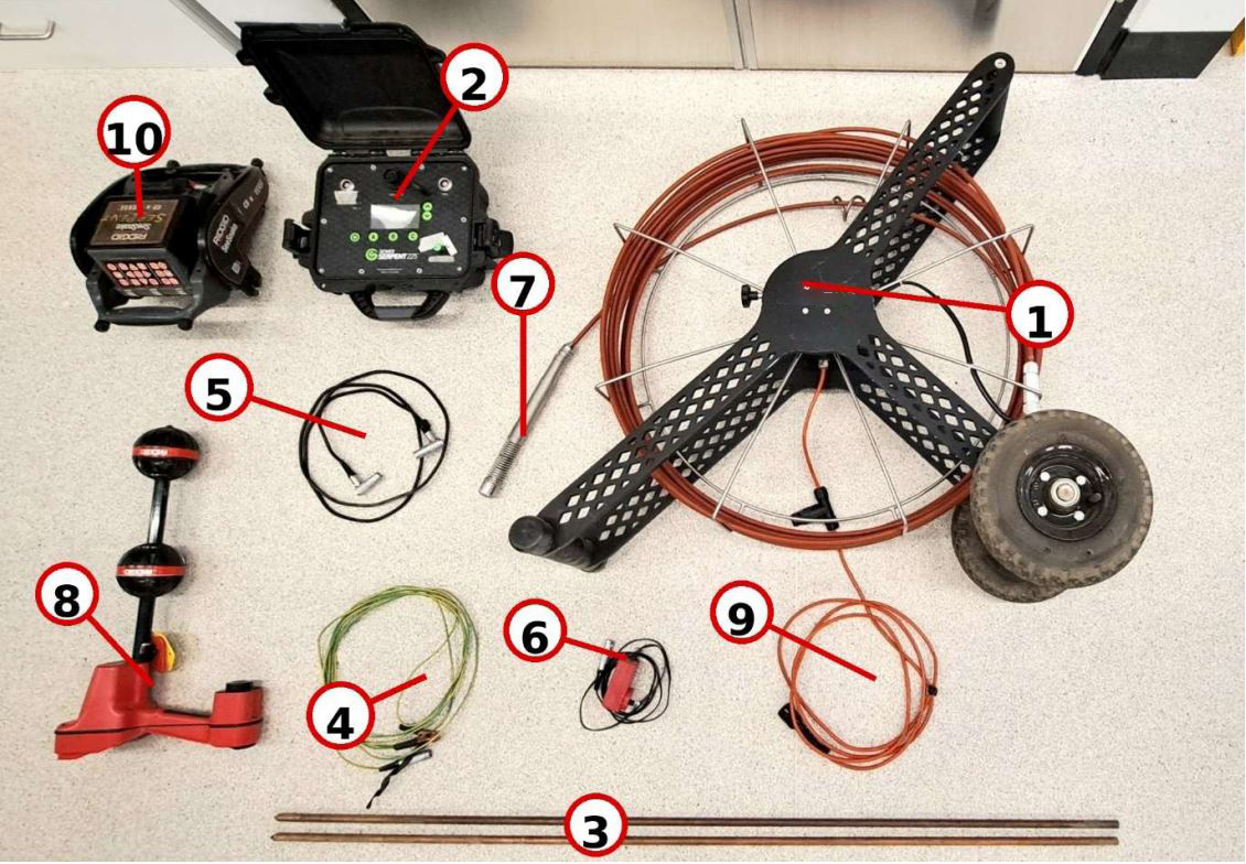
Alongside the measurement work, the team developed a Standard Operating Procedure for site testing. This documented the required equipment, setup process, safety considerations, operating procedure, troubleshooting steps, and records needed for repeatable testing.
The procedure included positioning the reel and control unit, placing grounding rods, flooding the pipe, checking earth and pipe signal integrity, zeroing the probe position, feeding the probe through the pipe, and reviewing detected leaks on the control unit.
This documentation was important because repeatability was a major part of evaluating the system. Poor grounding, inconsistent feed rate, wet conditions, or cable handling could all affect the quality of the test result.
Project Outcome
Outcome
The broader Sewer Serpent project was successful in demonstrating leak detection capability, but my specific measurement improvement work remained an open engineering challenge by the end of the placement.
The optical flow approach was a worthwhile proof of concept, but it was not reliable enough at realistic pushrod feed speeds. The follower-wheel encoder approach was more promising and produced encouraging readings after calibration, but the prototype still required further mechanical refinement to prevent slip.
The strongest outcomes from my work were the custom encoder interface PCB, the investigation into direct pushrod measurement, the follower-wheel prototype, and the engineering recommendations that clarified the next steps for future development.
Recommended Future Work
The most promising future direction would be a mechanically improved follower encoder system. A belt-contact or belt-driven encoder mechanism could increase the contact area with the hose and reduce the likelihood of slip compared with a single follower wheel.
Further improvements would include testing softer or higher-friction wheel materials, improving clamping consistency, sealing the electronics from water and mud, improving connector strain relief, and improving power reliability for field operation.
Sensor Evaluation
Investigated optical flow sensing and follower-wheel measurement as alternatives to reel-based distance estimation.
PCB Design
Designed a custom RP2040-based interface PCB with MOSFET outputs, visual indicators, test points, and connector breakouts.
Mechanical Prototyping
Developed a follower-wheel prototype with guide rollers and an adjustable clamping mechanism for direct pushrod tracking.
Field Testing
Supported test rig setup, operating procedure development, troubleshooting documentation, and practical system evaluation.
Project Reflection
This project was valuable because it involved real engineering constraints rather than a clean classroom problem. The system had legacy hardware, field handling requirements, wet operating conditions, cable strain, grounding sensitivity, power limitations, and a need to preserve existing functionality while testing new ideas.
Although my measurement subsystem was not fully resolved, the work still progressed the project by identifying what was unlikely to work, what was more promising, and what should be developed next. It also gave me practical experience in designing around existing systems, validating prototypes, and documenting recommendations for future engineering work.